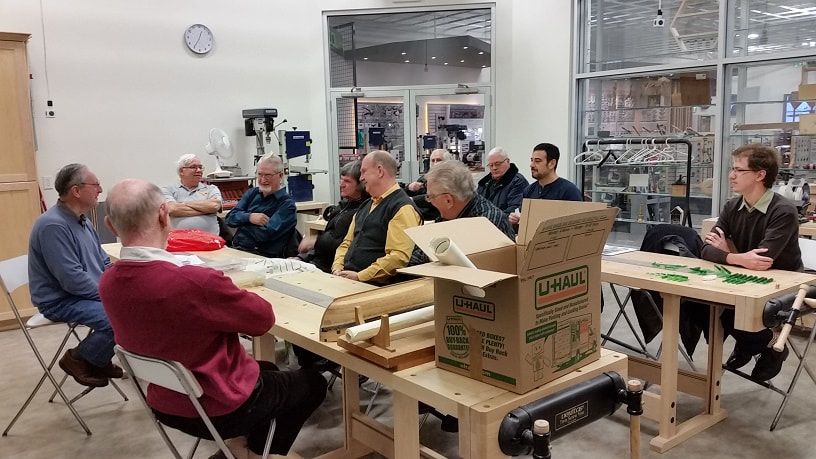
|
searchable LOG INDEX
download available to MSON members only (you need the password and it is not "1234") The privilege of membership! Non-members can still download and open the LOG PDF's below |
|
This month's meeting was held at Lee Valley Tools. The theme was Practical Ideas for Working With Wood with a presentation and demonstration by Phil M.
Phil showed us the thickness drum sander he designed and built, that was featured in the Canadian Woodworking Magazine a number of years ago. A downloadable PDF copy is available above. NOTE: the magazine artist took some liberties with his design and so their image does not fully agree with our accompanying photos. He uses it to sand his planks and other pieces to the proper thickness for his builds. It features a tilting base with a piano hinge on the feed side and tilt adjustment via a fully threaded carriage bolt through a blind nut on the other. The drum has Velcro face to which Velcro backed sandpaper to adheres (available in a variety of coarseness/grades). The drum is mounted with two pillow block bearings and is driven by a Vee belt connected to a 1/4 HP 1800 RPM 120 V 60 Hz electric motor suspended under the table. The dust cover is a separate piece that sits over the sanding drum. It has see through Plexiglas faces and a vacuum connecting spout on the top. He admits it is very good at making dust! He says the wood pieces must be held securely when feeding through and caught up on the outfeed side before letting go on the infeed side or it will throw out back at you. It is a good idea to stand to one side. He explained that if he was to do this again he would make the table shorter so he could get a better grip on shorter pieces. He also explained that the Velcro does make the sanding surface a bit soft so the wood must be fed through at a slow, consistent pace. Stopping the feed results in an unwanted divot. The use of calipers are a must to measure sanded thickness results in the work and make table height adjustments for additional passes. Phil then discussed how he bends wood. In both cases he places the piece in boiling water (in an old electric kettle) to make the wood cellulose fibres more pliable. The secret to bending wood is not the water, but temperature. Cellulose in the wood softens at about 200°F which is near the boiling point of water. The water is simply the vehicle used to increase the temperature. Once the wood has been shaped, it’s imperative to fasten the piece to the model with masking tape, to let the wood cool and dry. As it dries and cools, it will shrink and the cellulose will hold its new shape. The normal rule of thumb for soaking is about 1 hour per inch of thickness, so a 1/8" thick piece should soak for 1/8 of an hour or about 7-1/2 minutes. Phil uses a soldering iron with a flat nib passing it quickly over the surface of the wood (steaming the water in the wood) while he bends it by gently pulling up on one end. He also does it by clamping the part to a mould or form. He uses multiple clamps and leaves the part overnight to dry completely in the new shape. There is a limit to how much a part can be bent. We also discussed laminating thin strips of wood with white Weld Bond glue and bending immediately, clamping to a form, and letting it dry completely before removing it. The Weld Bond adhesive dries clear and if not applied too thickly will be completely invisible. Phil then described how he prefers to avoid painting his models where possible by choosing a variety of lumber that has the natural colour the model needs. He brought quite a variety of samples to show us, Swiss Pear, Holly, Bloodwood, Purple Heart, Amarillo, Poplar, Basswood (Linden), and Boxwood (Castello). He explained how he had some Holly that had aged (darkened) so he tried bleaching it with a diluted solution and it came back to it's natural bright white. Some woods are less suitable for models than others, some will keep an edge better than others, and some can be quite toxic, so you should know your wood and wearing a dust mask while cutting and sanding. Phil also showed how he uses rubber cement to adhere his paper patterns to wood for cutting. He brushes it on the wood and lays the paper over it, rubbing it down. Only applying it to the wood makes it easier to remove the paper. When done he peels the paper off, rubs the glue off with a crepe eraser (the type used to clean sand paper) and then scrapes a fine layer off the top of the wood with a sharp blade to remove any glue residue. He also discussed his preference for Viking band saw blades. He finds them to be more flexible and last longer. He finds them to be more flexible and last longer as they are a bi-metal composition. Because they are installed at a low tension, there is less wear on the tool and they ease the problem of wood moving away from the fence as it does when cutting thin stock with steel blades. These blades are made in Ontario and are available from Lee Valley. Phil had brought in his 16 gun model (under construction) of the USS Lexington (1776) a two masted Brig which can be seen in the photos above. He has done a fine job on her to date. The model is being scratch built following plans by Clayton Feldman and represent an amalgam of a type of small, armed cutters, sailing on the Great Lakes circa 1800. Ray had brought in his model of the Isabel, a North Sea fishing trawler that had been converted into a personnel sail boat. He had seen the vessel while on vacation and took a few photos. Knowing the length after speaking to the owners he then scribed lines on the photo to convert measurements so he might build her. The hull was shaped from a solid block of wood, as was the mounting base. Alan brought in a sample of two methods for mounting his keel to his build board and eventually to a display board.
One method used is a simple #6-32 hex nut embedded in the top of the rising wood as shown in the fore portion of the photo to the above left. The nut is a thick as the rising wood which is sketched in pencil at the end of the block. In Alan's mind, there isn't much top wood left to glue the frames to. The outside flats of the hex nut could be filed narrower to reduce the size of the pocket as he had seen volume 1 of 4 in the The Fully Framed Model, but he devised a different approach as seen at the back end of the photo. Alan purchased some #6-32 Helicoil threaded inserts, 304 Stainless Steel, and a length of #6-32 zinc plated threaded rod. The dissimilar metals will avoid any degree of galling over time. He drilled a #29 (0.136" diameter) clearance hole through the rising wood/keel/false keel assembly for the threaded rod (0.132" diameter) . He then drilled a #15 (0.180" diameter) hole down through the rising wood for a depth of 1/4" for the Helicoil insert (0.1785" outside diameter). The threaded rod was passed through the hole, thread coated with petroleum jelly (Vaseline) and the helicoil insert threaded onto it. A two part epoxy adhesive was applied to the outside threads of the insert. The Vaseline kept the glue from leeching through the thread and gluing the insert to the rod. The rod was pulled to draw the insert into the stepped hole. Then the rod was removed and the insert left until the adhesive dried and cured. The tab was broken off the insert the next day, but actually could have been removed prior to the assembly. This method leaves a tiny hole at the top of the rising wood, and more wood to glue frames to. Also worth mentioning is that the hex nut has 3.4 threads where as the inserts have 7 full threads of holding power. As a mechanical designer, Alan appreciates that it takes 5 full threads to develop the full holding strength of a mechanical threaded assembly. As an after thought, the pocket could be drilled slightly deeper so the exposed hole on the top face of the rising wood could be closed with a plug of wood providing a full glue surface for frames.
0 Comments
This month's meeting was held at Lee Valley Tools. The theme was Capstan and Windlass construction with a presentation and demonstration by David A. With the aid of images found in Volume II of The Fully Framed Model, David explained the different parts of the Capstan and Windlass, and then proceeded to demonstrate how to mark off the square stock to create a ten or twelve sided spindle for the Capstan, or the eight sided (octagon) spindle of the windlass. David has a simple home made jig with a stop at one end, and a shallow V-groove along the length of the plate to hold the edge of the stock as he shaves away the corners, down to his pencil mark, with a very sharp chisel. The following short video shows his technique.
Then David explained how he uses the same concept to shape his masts. He had a mast that was painted, and described how he lightly scores around the trunk with a sharp knife edge to stop his paint from bleeding beyond the painted portion. He uses shoe dye as the black paint, and a Q-tip as the applicator. David also brought in a 1:12 scale Norwegian Pram Dinghy, part of a kit he is creating for Model Expo. Ray had brought in the half model he is repairing. It is missing the rudder which had fallen off and been lost. Ray had made a new half rudder which he had shown us, but it is unfinished (needs sealing and painting) before he mounts it. He seals his wood pieces with water based acrylic sanding sealer prior to any finish work (painting). This is then sanded incrementally increasing the grade of sand paper until he is happy with the smooth finished quality of his efforts. Alan brought in the rudder he scratch built for his ship. It is 1:64 scale. The two main pieces of the rudder blade (5'-6" x 33 feet) are Costello boxwood. He chose two pieces of different shades of wood in an attempt to accentuate the tabling joint between them. There are two tiller holes in the head. The lower hole would have a tiller installed that is controlled by ropes and pulleys connected to the ships wheel. The upper hole is for a spare tiller in case the lower tiller, ropes, or ships wheel are damaged. They are 12 inches square inboard and tapered down to 1/3rd the width of the head of the rudder on the outboard side. The 6 inch thick sole plate and 4 inch thick backing plates are Hemlock. The faux 1-1/2" diameter bolts are black monofilament fishing line.
This month's meeting was held at Lee Valley Tools in Niagara Falls, and the theme was General Marine Modelling. Alan brought his scratch build of HMS Bellerophon back to show that he had completed the installation of the forward cant frames. Next he will be installing the spacer chocks between the frames to stiffen it up, then pinning the heel of each frame to the keel to lock them in place prior to fairing (sanding) the inboard and outboard sides of both the aft and forward cant frames. Alan also discussed with members how to properly position the pedestals prior to his drilling holes through the keel for four 6-32 threaded rods. David and Ray suggested he use his existing 3D model, add the masts, bowsprit and jib boom and then it was simply a question of what looked best taking into account the overall length. So Alan did this when he got home and the results are posted above. David A. brought Greg H.'s model of HMS Speedwell back to show his progress with David's carvings on the bow, stern quarters and transom of Greg's ship as can be seen in the slide show above. Bob R. brought in his model of the Danish frigate Jylland (1860 - 1908) that he has been working on. He had replaced some of the decking and was unhappy with the two tones due to old and new pieces but members encouraged him to just wait as it will all turn to one shade in time. He had also showed us progress with deck coamings, grating, and doors. He has also made a jig in readiness to fabricate ladders. These are displayed in the slide show above. John brought in his Iroda Solderpro 50K soldering pen kit to show the group. It is fueled with Butane, having a power range of 30W - 70W heating capacity. It is a nice small, easily handled, pen. John also showed us a sheet of his photo etching parts for his König Class Battleship. He will be giving a demo on photo etching in April. John also brought in a variety of bottled epoxy resins used to effectively recreate realistic looking water and mud puddles so we could see what kind of items are available to modellers. Dave R. demonstrated the use of a ticking stick, a device used by ship builders to reproduce shapes. the best way to appreciate the simplicity and accuracy of this item is to watch this YouTube video.... https://www.youtube.com/watch?v=Cd2LY857oTY
Dave intends to use this for inlaid pieces in the amazing musical instruments he makes. This months meeting was held in the seminar room at Lee Valley Tools on Niagara Falls, Ontario. The theme was Digital Photography for Scale Models with a presentation by Alan. With various cameras, lenses, lighting and slides, Alan discussed and explained how best to control your composition, lighting and equipment to get the best image possible. He explained the difference between JPEG, TIFF, RAW and PNG file types; which is best and why. He also discussed AWB (auto white balance) HDR (High Dynamic Range) and Stitch Assist. Then there was the secret of aluminium foil! If you would like to know what it all means download the PDF here...
Don brought in his newly acquired 1:48 scale Mayflower kit by Graupner to show the group. The box contains many stamped balsa wood parts that need to be cut out (scroll saw). Instructions are mostly in German but Tijs offered to help with translations. Tijs brought in a scale replica of a traditional old style Killick Anchor he purchased while in Newfoundland and Labrador. The anchor is wood with a heavy stone trapped in it for weight. This rock would be 1 to 40 lbs. (0.45 to 18 kg) in mass to hold it in place on the sea bed. Alan brought in his 1:64 scale scratch build model of HMS Bellerophon to show the progress on his forward cant frames and a couple assembled frames on their templates to describe his process.
The model is resting on a travelling support board (similar to Ray's) which he had made the night before because every time it travels some frames are knocked off. Not this time though! The model was also used as part of his digital photography lighting demonstration.
John had brought in has four gun models (3 x 9 pound and 1 x 12 pound cannons) that were in storage. The heavy metal barrels were purchased at the gift shop at Ft. George in Niagara on the Lake (NOTL) more than 15 years ago. The naval style carriages were made from scratch and the infamous metal Garrison carriage (in the centre) was purchased with the barrels. John pointed out that the Garrison carriage was found to be a terrible idea as if it took a direct hit it would shatter into many deadly pieces. John added the royal cyphers to each barrel prior to paint by applying tiny dots of Weld Bond to build up and shape the images as he had demonstrated last May (see blog entry below). The cannon balls are ball bearings. They are temporarily displayed for us at our meeting on a piece of cardboard, being held with double sided tape. At last month's meeting David had brought miniature figures he had been carving and mentioned the micro chisel set he uses to produce this work. Alan had taken the Admiralty Model Carving Workshop last May in NOTL and David had shown everyone the set then. As Alan will be carving his own figures for his build he purchased a set. These are excellently hand crafted micro chisels, 23 in all, made by Mihail Kirsanov of Russia. If anyone is serious about wanting to purchase a set contact Alan via this website for information. At this same workshop David had shown participants a fully articulating aluminium vise that he uses when carving small pieces. Alan's was purchased from Amazon. Ray had completed his scratch build of the Shamrock V (1:72 scale). He had been working on this over a period of about 1-1/2 years and was happy to show it to us proudly displayed at a side window. She measures 119 feet (19.8" at scale) long with a 20 foot (3.3" at scale) beam and 153 foot (25.5" at scale) mast height. The actual Shamrock V was the last of the series of five racing yachts built by Sir Thomas Lipton (of Lipton Tea) in 1930 for the America's Cup challenge... and is still being sailed today. Ray also showed us the silhouette of a scaled down man he has been busy shaping ( cut and file ) from a piece of brass. He intends to mount this on the mounting base of the model to act as a visual aid to realising the full size of the build. This month's meeting was hosted by Lee Valley Tools in Niagara Falls, Ontario. The theme was Resistance Soldering with a presentation by Ron. Ron briefly reviewed the different types of soldering and then explained the concept of Resistance Soldering as used in modelling in some detail. Following is a link to his notes for the presentation: resistance_soldering_by_ron_c._sep_2019.pdf He explained that it is the Amperage and not the voltage that is important in resistance soldering. A good ground is a must! Droplets of solder are applied via syringe an probes are located to touch the base material above and below the droplet to concentrate the heat at the solder. Heat sinks can be used to draw heat away from areas you do not want heated as it might cause damage to that area (i.e. such as a low temperature surface coating) Ron had also brought back his schooner the Scottish Maid (1839) that we had last seen at our May meeting. He has since been adding items onto the deck and the anchors at the bow as can be seen in the photos below. He pointed out that one noticeable feature is the way the bow sweeps forward above the waterline to increase the capacity in the forward hold, as ships were taxed according to their length on the waterline. 12 David A. brought in his friend Greg's model of the 8 gun ketch rigged sloop HMS Speedwell of 1752 (1:48 scale). David has been working on the carvings for Greg as can be seen below. The wood is Costello and the pieces are mounted to soft backing pieces with white glue for handling while carving. Once completed they will be removed from the backing boards by soaking them in Isopropyl Alcohol (rubbing alcohol) to dissolve the glue. All David's carvings are by hand using a set of miniature chisels. He does not use rotary powered tools. David described how he glued sandpaper to the stern quarters so he could sand the backside of his carving stock to fit the specific shape of the hull before he started these particular carvings. Ray discussed his model of HMS Ontario and his contribution of a chapter about his model build to the book written by Jim Kennard about the discovery of the sunken wreck of the ship in Lake Ontario. Ray does not get a commission on the sale of this item. If you are interested, the book can be ordered at: https://nmglstore.org/collections/frontpage/products/pre-order-shipwrecks-of-lake-ontario-a-journey-of-discovery Ray also mentioned that a UK company is developing one of a series of the “Drain the Oceans” videos for National Geographic. This will show how CGI will be used to “drain Lake Ontario” to reveal the wreck of “HMS Ontario” on the bottom. Photographs of Ray’s model will be used as the basis for the computer modelling David R. brought in two new book discoveries with excellent images of ship and boat building details. 1) Wooden Ships - The Art, History and Revival of Wooden Boatbuilding by Peter Spectre and Douglas Larken 2) The Building of Boats by Douglas Phillips This month's meeting was hosted at a club member's home in Welland. The theme of the meeting was 3D Liquid Resin Printing with a demonstration by Brandon Brandon set up his 3D printer outside so any fumes could be safely exhausted. He has a home built exhaust duct with a duct fan that he uses in his apartment that he had brought to show the group. Brandon has show cased a number of items he had printed over the last few months so we were all familiar with what it could do. First he showed and described to us SKETCHUP, the modelling program he uses. The older versions of this were a free download but they are presently starting to charge for this program. The 3D model is saved as an STL file for the next step. He then showed us a 3D filament type printer (JG Aurora A5) and described this system. It uses a 1.75 mm PLA or ABS material filament on a spool that feeds into a hot nozzle (approximately 200°C) and extrudes it onto a hot plate (approximately 60°C). The hot plate moves front to back as the nozzle moves side to side and rises to deposit new layers to build or print the item from the plate upwards. Brandon showed and described to us the free Ultimaker CURA SLICER program that is used to change the STL file into a language the printer can use to print the slices or layers of the model. We then went outside to see his 3D Resin Printer at work. As described in our March blog, his is an SLA UV acrylic liquid resin 3D printing machine made by Any Cubic Photon. This printer does not operate hot. The liquid resin is poured into a containment reservoir and the head moves up and down approximately every 7 seconds as the part is built up in layers hanging from the underside of the head. Individual ultraviolet (UV) light beams are turned on/off to harden 20 micron size droplets of resin onto the underside of the head of the machine where the slicer program tells it to build the part. As it dunks new droplets and layers are built downwards from the head (upside down). Because of the extreme accuracy of the UV lighting it can recreate much finer detail than the earlier mentioned filament style printer. Brandon explained that the resin chemical should be handled with considerable care. He wore gloves throughout the process and the prints were not handled with bare hands until after a 20 minute soak in rubbing alcohol followed by a clean water rinse. Phil M. had brought in his model of the Spanish (Basque) Whaling Galleon San Juan, considered to be the oldest Canadian Ship wreck. The San Juan had sunk off the shore of Labrador in the Straits of Belle Isle in 1565. She was 90 feet long and had three masts. There has been considerable progress since we had last seen her. Phil explained that all wood used in his model was Swiss Pear and the finish used determined the colour. He had used clear coat on the deck planks. The actual ship had hardwood (oak) below a particular elevation where strength was required and softwood (fir) above that elevation to reduce weight. He decided to leave the port side open to allow the frame work and interior to be viewed. David A. brought in a booklet he had supplied to people that took part in the Admiralty Models Workshop he held at Queenston (near Niagara Falls in Ontario) last weekend where he had taught Carving Techniques for Ship Modellers. Alan had participated in the workshop and showed club members the Plasticine maquette (a hand made 3D model of the parts to be carved) he had made that was to be used as a reference to help visualize the height, depth and shadowing effects before any chisel touched any carving medium. We had then carved the items into high density foam (to simulate wood) at half the scale of the model. This months meeting was held in the seminar room at Lee Valley Tools in Niagara Falls, Ontario. The theme of the meeting was Relief Sculpting methods for Model Details with a demonstration by John. John began by explaining the difference between additive and subtractive sculpting. Subtractive is the process of removing material from a base material, as in carving in wood or chiselling in stone, to reveal an image. Additive is simply depositing material to build up an image from a base material. John demonstrated his additive method. A fine pointed implement, steady hand and practise are all that are required. John demonstrated on a piece of blackened (painted) cardboard using Weld Bond and a very fine paint brush. He says you must use a fine tipped implement and has also used toothpicks. The liquid Weld Bond is brushed or dabbed onto the base material in small quantities, then allowed to dry a bit or thoroughly if you prefer. Liquid Weld Bond is white but when dry or cured it is clear or transparent The Weld Bond will slump or settle a bit as it dries. When ready simply apply more material to build up the sculpture. If you've added too much it can be chiselled, filed, or sanded away once cured. If you've made a mistake it can be wiped away before it is cured with a bit of water as it is water soluble. Once cured and completed (sanded to shape) the sculpture requires a primer coat of acrylic paint. John pointed out that the enamel spray paint (Beauty Tone) he once used on a plastic model might have contained solvents or generated heat which had resulted in the deformation of the plastic, whereas he has never experienced this with acrylic spray paint. The dried primed sculpture can then be finish painted and augmented with highlighting as John had did with one of Brandon's 3D resin printed cannons. The Royal Cypher and cast reinforcement rings of the cannon barrel were highlighted with a light brushing of grey acrylic. The paint was lightly loaded onto a brush and then the brush was wiped lightly on a paper towel to remove most of the paint. The areas to be highlighted were then very lightly brushed grey. This was later augmented with a dash of Gun Powder Black (black paint pigment) added via paint brush to the hole of the firing pan and around the muzzle for touch of realism. Ron had brought his schooner Scottish Maid (1839) that he is presently working on. Both the hull and deck planking are completed and have been fitted quite nicely. He is now working on the standing rigging. We are all looking forward to seeing his progress at our next meeting. Tijs brought in kit model of the Roger B Taney, a US Revenue Cutter (1833-1858). Next to it was an unrelated smaller row boat he had made. Dave brought in a couple of books to review... 1) Franklin's Lost Ship - the Historic Discovery of HMS Erebus It tells you everything except exactly where the ship is as it is a protected site. 2) The Anatomy of Sail - The Yatch Dissected and Explained It is and does exactly as the book title claims - very informative. Dave also brought in his new Apple Pen to show how he uses it with his IPad to add notes to images. He can also use it to add voice files. In this case he uses it to add a music file to images of his Native American flutes to keep a permanent record of their range capability. He also brought in his second flute to show how he added a thin inlay to it to hide the seam joint on the sides. He had to carve the grooves freehand as the compound angle and curves could not be followed by a router. Ray brought in a new addition to his tool chest to show the group. He had just acquired a Proxxon PS13 Sanding Pen. It comes with four straight and four angled pad holders and uses self adhesive sanding pads sold by Proxxon. The cord has a special 3 prong plug that works with the 12VDC transformer that Proxxon sells separately. The unit sands in a linear (side to side) motion, not orbital, and is quite suitable for models and tight locations. This month's meeting was held at the amazing Community Centre in beautiful Niagara on the Lake... it was a miserably wet and cold day. The theme of the meeting was Air Brushing with a very detailed and informative presentation by Pat. He explained that the compressor was the heartbeat of the process so those interested should invest in a good one. His included a regulator and water trap. Pat described two types of air brushes: the single action and the dual action. Basically the single action is that you simply depress the button and it opens the valve to allow the compressed air to pass through. The dual action requires you to depress the button and pull back on it so it acts as a safety device. The dual action is good for painting pictures and fading out. The air brush can have a cup or a jar to hold the paint. The drip cup is used for small parts as it holds a smaller quantity of paint. With the compressor powered ON you need to do a test spray to set the atomizing rate with an adjustment screw near the discharge orifice/needle. Paint is applied to the part in light "dust" coats, starting off the part, passing over and beyond the part so as not to build up paint on the part at the start and finish points. It is best to allow a short drying time (about 5 minutes) between coats. Most paints require thinning which is usually done at a rate of 1/3 thinner to 2/3 paint. He mixes his in a small plastic cup (shot glass size) with a stir stick. Once thoroughly mixed he pours it into the cup or jar. He mentioned that you can blend like paints (enamel with enamel or acrylic with acrylic) but do not mix unlike paints! Pat talked about masking showing us thin flexible tape and tape with waxed paper attached to one half providing over spray protection. Holding parts for painting can be tricky. Pat uses a homemade Medusa looking NEMA wire and alligator clip assembly on an heavy base. He also employs several types of tweezers to grip small parts. (see photos below) Cleaning up is an important step as it will insure your equipment is in good working order next time. You do not want to invest in a good air brush gun only to find it clogged up with dry paint. Pat uses alcohol, enamel cleaner, extremely fine (0000) steel wool, lint free Kimtech Wipes and small pipe cleaner type dental cleaners to keep his gear sparkling. Once again - sorry you missed it! Brandon brought his 3D prints back in to show some of them painted flat black. He also had a set of guns printed for a 74 gun war ship of circa 1780's (without the breeching rope ring): 9 Pdr short, 9 Pdr Long, 18 Pdr and 32 Pdr. This were brought as examples to the meeting for Alan as he is looking for a supply for his model. Ray brought in his completed half hull of the MUSIGNY at 1:16 scale. He has done a fine job of painting the hull. The mounting board and finish edging are teak. He also showed us the back side to allow us to see the strong hanging brackets and lower bumper pads added to protect the wall and help the model rest properly against the wall when hung. David R. brought in a couple of new items he has added to his work shop. One was a LED illuminating magnifying visor he had purchased from Lee Valley Tools. It comes with a variety of magnifying clip on lenses and holds two at a time. They also flip up and out of the way when required. They were advertised as a limited quantity and I cannot find them on the website. The other was a centre marking gauge used to mark the centre on round stock. He purchased this from Busy Bee Tools. www.busybeetools.com/products/center-finder-woodworking.html He also brought in a Native American Double Drone Flute he had made for his daughter. It was a beautiful looking and soft sounding instrument. He described in some detail how it was made out of pine in two halves. How the two chambers are divided and the air is slowed down and directed. How the holes are located and the wall thinned to create the perfect notes. His was described as pentatonic which for the non-musician means every note is perfect pitch. Here is a link to a website that further describes the instrument. www.flutopedia.com/faq.htm Alan had brought in his incomplete bowsprit, jib boom and jack staff assembly for his 1:64 scale HMS Bellerophon build to show the group. He is presently working on the forward cant frames and decided to build the bowsprit to test fit the opening made through the bollard timbers and at the head of the stem post. The 7'-6" x 11'-3" Union Jack is water thinned Acrylic paint brushed onto Silkspan. The representation is dated prior to 1801 union with Ireland (less the FitzGerald Red Saltire, aka St. Patrick's Cross) and it bent to the halyard with white marline. The incomplete assembly, temporarily held together with elastic bands, will go into storage until it is ready to be finished and mounted onto the ship model. Although Tijs could not make the meeting he had forwarded photos of his recently completed model of the ROGER B TANEY, a US Revenue Service Cutter (Morris-Taney Class) dated from December 1833 to January 1858. (Photos below) This month's meeting was held at Lee Valley Tools in Niagara Falls, Ontario, Canada. The theme of the meeting was 'Spiling Planks' and the presentation was made by David Antscherl. Handouts (copyrighted material) were provided to those in attendance. An earlier version of this handout can be downloaded from: http://modelshipworldforum.com/ship-model-framing-and-planking-articles.php David explained how to line off the hull. This was how to measure and divide the hull surface in preparation for planking. Following this was how to line out the hull; a mechanical, then artistic, process to provide the run of planking. Finally the actual process of spiling was demonstrated; this determines the shape of each plank's edges so they nest tightly and conform properly to the shape of the hull without stress. The presentation was fascinating... sorry you missed it. We had a special visitor this month. Mr. Grant Wilson of Welland presently builds model airplanes (ships of the sky) but had at one time built model sailing ships. One in particular was Old Ironsides, the USS Constitution. She is a wooden hulled three masted heavy frigate. Launched in 1797, retired from active service in 1881 and is still afloat today, berthed at Pier One in Boston. Grant brought in a full set of Smithsonian prints from which he built his model. These were offered free to any member and were eagerly accepted by Dave R. Brandon had brought in pieces he had 3D printed with his SLA UV acrylic liquid resin 3D printing machine made by Any Cubic Photon. The surface finish and detail was quite impressive. He reports the material can be sanded and painted. Dave R. brought in two books to show the club. He had purchased these at The Book Depot in St. Catharines. Both were less than $10 each and can be found in the History Section. The Warship Anne (HMS Anne - 70 gun 3rd rate ship of the line 1678-1690). The Voyage of the Beagle (the journal of Charles Darwin onboard HMS Beagle, originally publish in 1839). He also brought in a miniature African Kora, a lute-bridge harp he had made. It is a beautifully constructed and sounding musical instrument with drum sticks for handles, a bowl from IKEA, and the two top coloured strings (blue and green) were lines for a grass trimmer! Once again it is not a boat but everyone had to pluck it. Tijis had brought in photos of a blanket box he'd made for his daughter and also an update photo of his rebuild of the Bluenose II as seen above.
Ron brought to our attention that the annual modelling show HERITAGECON 13 is in two weeks (24 March 2019) at the Canadian Warplane Heritage Museum in Hamilton, Ontario.
For more info got to their website: http://www.heritagecon.com/index.html |
Archives
September 2023
|